Check out the other AutoMap Articles:
Part 1 - Part 2 - Part 3 - Part 4 - Part 5 - Part 6 - Part 7 - Part 8 - Part 9 - Part 10 - Part 11 - Part 12
Symbol Rotation
AutoMap is a system of automated drafting tools that can help you organize many tasks. In general, the AutoMap routine allows you to work with your field codes and to assign attributes to points and linework as they are drawn in the CAD file.
Some functions of AutoMap include:
- Assigning a symbol of your choice on each point based on description
- Move descriptions, points, elevations, and points to a layer of a given name
- Scaling a symbol to further customize each object
- Connecting points using the line connectivity function
- Further customizing linework with specific layers and line types
In this article we will create a new AutoMap entry that will insert a symbol on a point. Further we’ll look at how you can add codes to your description when in the field to tell MicroSurvey CAD how to draw the symbol. We’ll start by adding a point called “Power Pole” – note the point number of this point; in this case it is point 7.
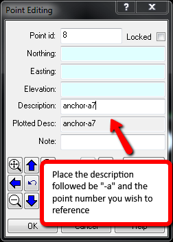
You can specify in your description how AutoMap should deal with symbol insertions.
Symbol Align (-A)
You can have your symbols automatically rotated to align with any point in your drawing, you indicate this in your description. By adding “-a7” after the point it will tell the point to be aligned with point 7 (the power pole).
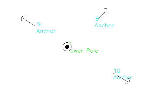
Now do this 2 more times each time referencing the power pole point to show the anchors from the power pole.
The result: each new symbol is aligned with the reference point.
Check out the other AutoMap Articles:
Part 1 - Part 2 - Part 3 - Part 4 - Part 5 - Part 6 - Part 7 - Part 8 - Part 9 - Part 10 - Part 11 - Part 12
Olivia Floyd
Comments