Check out the other AutoMap Articles:
Part 1 - Part 2 - Part 3 - Part 4 - Part 5 - Part 6 - Part 7 - Part 8 - Part 9 - Part 10 - Part 11 - Part 12
Assigning a Symbol to a Field Description
AutoMap is a system of automated drafting tools that can help you organize many tasks. In general, the AutoMap routine allows you to work with your field codes and to assign attributes to points and linework as they are drawn in the CAD file.
Some functions of AutoMap include:
- Assigning a symbol of your choice on each point based on description
- Move descriptions, points, elevations, and points to a layer of a given name
- Scaling a symbol to further customize each object
- Connecting points using the line connectivity function
- Further customizing linework with specific layers and line types
In this article we are going to discuss how to assign a new symbol to an existing description or to create a new entry all together.
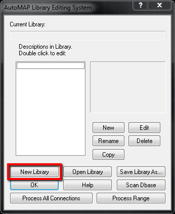
Open AutoMap editor by either typing in the command line "automap_editor" or opening it from the traverse ribbon (Traverse -> AutoMap Library.) For this exercise we're going to create a new AutoMap by clearing the default AutoMap.
1. Press "New Library:"
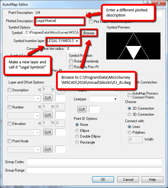
2. Create a new description code, name the code LM for legal marker and enter the settings below:
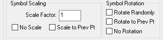
3. Take note of your options for scaling.
If you set the Scale Factor to 1, 0 the initial scale at insertion will be 1.
If you check on "No scale" the symbol will be inserted with no scaling.
If you append -s# to the field code another rule is applied. See this article on scaling symbols with field codes.
Symbols will be scaled as they are inserted (unless "No Scale" is selected or a -s has been appended to the field code) according to the following project variables:
- In a US feet or Feet Project: original dimension x .01 x Drawing Scale Factor x Scale Assigned by AutoMap
- In a Metric Project: original dimension x .001 x Drawing Scale Factor x Scale Assigned by AutoMap
4. Modify the text offsets as shown:
5. After you pick OK and close the AutoMap Editor you will see that any points with the "LM" description look no different. Update your drawing after the AutoMap changes by using "rescale complete drawing." You can do this by typing in the command line ms_rescale or under the MSPoints -> Re-scale Complete Drawing.
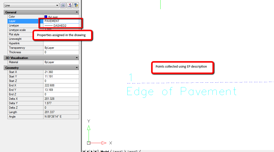
The Result: 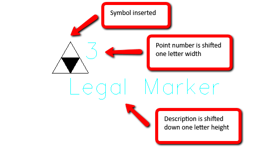
Check out the other AutoMap Articles:
Part 1 - Part 2 - Part 3 - Part 4 - Part 5 - Part 6 - Part 7 - Part 8 - Part 9 - Part 10 - Part 11 - Part 12
Olivia Floyd
Comments