This article provides a reference for the online Instrument Settings calculator. The calculator inquires as to your known instrument specifications and computes the correct Instrument settings using the most commonly accepted methodologies.
See this link to access the calculator
See this link for information about the formulas used to compute the results.
Number of Sightings per Target
Select from this pulldown to indicate the number of observations to a single target that are averaged when you compute and then enter an angle or direction input in STAR*NET. It is assumed that distances and zenith angles will also be the result from this averaging process.
 |
This setting will be used to compute constraints for the following measurement types:
|
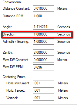
DIN 18723 or ISO 17123 Directional Accuracy:
This is the value we usually refer to when we designate an instrument as a (for example) "1 second instrument." See this article to learn more about the Din18723 standard.
ISO-17123-3 states: “The measure of precision of theodolites is expressed in terms of the experimental standard deviation (root mean square error) of a horizontal direction (HZ), observed once in both face positions of the telescope or of a vertical angle (V) observed once in both face positions of the telescope” These standards rate the accuracy of the average of a direct and reverse (face 1 and face 2) observation.
Why would you Multiply by √2?
If direction measurements are input into STAR*NET as single direct OR reverse observation to a target (the usual approach taken by converters) the DIN 18723 or ISO 17123 value should be inflated by multiplying by √2 before being used to define the direction setting.
 |
This setting will be used to compute constraints when directions are included in the following measurement types:
|
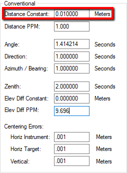
This value is published with your instrument specs and gives an indication of the accuracy of slope distance measurements at any distance. This constraint has the same effect at any distance.
 |
This setting will be used to compute constraints when distances are included in the following measurement types:
|
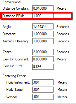
This value is published with your instrument specs and gives an indication of the accuracy of slope distance measurements. The "Parts per Million" specification is added to the EDM Constant and has an increasing effect on your measurement confidence as the distance increases. The longer the distance, the more the EDM PPM inflates the expected standard error for the measurement.
 |
This setting will be used to compute constraints when distances are included in the following measurement types:
|
This value is rarely computed from instrument specifications. In most cases this value constrains measurements input as given directions that come from another source and thus you have to apply your own judgement as to what the standard error should be.
 |
Some examples to illustrate your application:
|
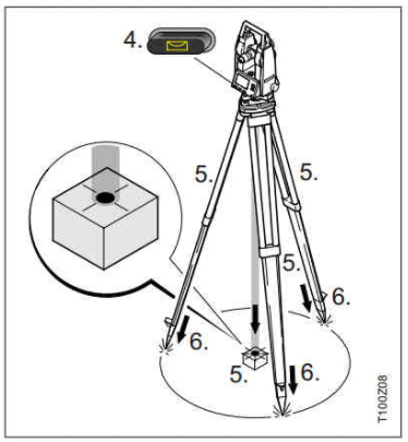
This value may be estimated or may be found in the specifications for your tribrach (depending on the manufacturer.) This value indicates the accuracy with which you can position the instrument above the point being measured. This value is minimal or zero if you are "forced centering" the instrument over the point by directly connecting to a mechanical bracket. If you are setting the instrument on a tripod you will want to consider factors such as:
- your visual skill at positioning a laser plummet or optical plummet cross hairs over the point
- the instrument height
- the accuracy of the optical plummet or laser plummet
It is typical to allow for 1 mm to 5 mm or .0003 to .0015 feet when using a tripod
 |
This setting will be used to compute standard errors for any measurement involving a total station and a horizontal component.
|
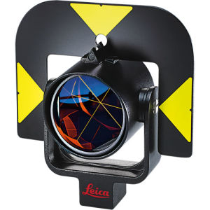
This value may be estimated or may be found in the specifications for your tribrach, prism or prism rod (depending on the manufacturer.) This value indicates the accuracy with which you can position the target above the point being measured. This value is minimal or zero if you are "forced centering" the target over the point by directly connecting to a mechanical bracket. If you are holding the target on a tripod or prism rod you will want to consider factors such as:
- your visual skill at positioning the target over the point
- the target height
- the accuracy of the optical plummet or rod level bubble
It is typical to allow for 1 mm to 5 mm or .0003 to .0015 feet when using a tripod and more when using a rod
 |
This setting will be used to compute standard errors for any measurement involving a total station and a horizontal component.
|
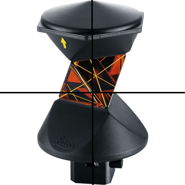
This value may be estimated or may be found in the specifications for your instrument. ATR, or Automatic Target Recognition centering error is only considered when using a self-aiming total station and only in high precision work. ATR centering is used to inflate target centering error to provide a final target centering value.
If you don't want to consider this value, set it to zero.
 |
This setting will be used to compute standard errors for any measurement involving a total station and a horizontal component.
|
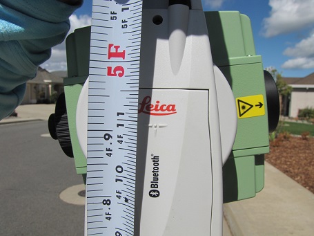
This value is usually estimated by considering the accuracy with which the Height of Instrument or Height of Target is mechanically measured.
It is common to estimate this value as 2 mm or .005 feet.
 |
This setting will be used to compute standard errors for any measurement involving a total station and a vertical component.
|
James Johnston
Comments