With our CAD products, some users have found that their Azimuth or Angle numbers do not match with what is being labeled or inputted in the command line in their drawings.
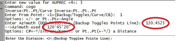
Take this example in which the 120.4523 was inputted, but only 120° 45' 20" was displayed when the AUPREC value was set to 3:
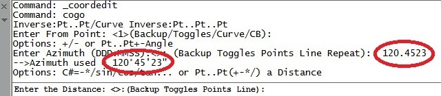
Now if we were to run the AUPREC command, we could change this value. In this case, we are going to change its value to 4 to show down to the nearest second:
![]()
If you look at the Angular Value again, you will notice this:
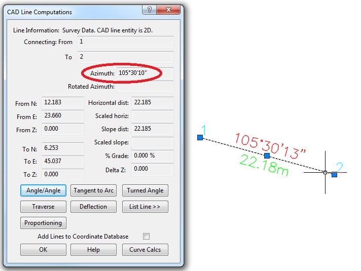
Also to note, the AUPREC value will affect what is shown in the CAD Line Computations dialog. Take this example, in which the Azimuth does not match the Labeled Bearing:
Now if we run the AUPREC command and change the value to 4 as we did in the example above, you will see this:
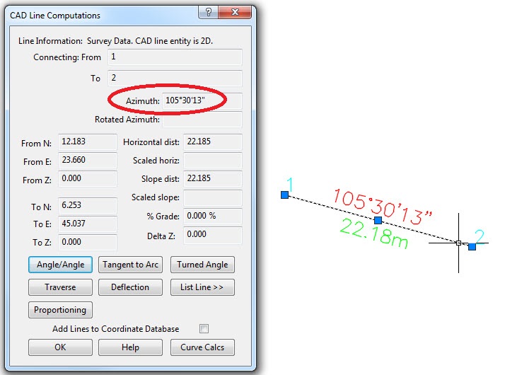
The AUPREC or Display Precision is a CAD function, not a MicroSurvey function. Therefore, if someone were to change that setting on a drawing, then send it to another user, that user might run into this issue when labeling lines or imputting values in the command line. As shown above, this is just a matter of how many decimals are being displayed, i.e., the Display Precision or AUPREC value.
*Note: If you would like to change the precision of your Linear Unit Precision, change the "LUPREC" value in your project by typing "LUPREC" in the commandline and setting the precision value.
Chris Clemente
Comments