The sizing and style of simple point nodes in all CAD products is are controlled by two variables that are stored in the dwg file:
PDSIZE: Controls sizing of the point node. Setting to 0 and up sizes the point node in real world dimensions. (ie: if you set it to 1 it will appear as if it were 1 foot or 1 meter in radius in your drawing) Setting to any negative number causes the node radius to a percentage of the screen size so the appearance will be changes as you zoom in and out, much like IPNs do.
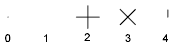
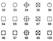
PDMODE: Controls the "style" of the icon used to represent the point node.
Possible values for this variable:
0 to 4, 32, 33, 34, 35, 36, 64, 65, 66, 67, 68, 96, 97, 98, 99, 100
NOTE: Watch out for PDMODE 1 which makes the point node completely invisible!
NOTE: Some CAD programs require a manual regen before point node appearance is updated.
Please note that these variables are stored in the CAD file. When you receive a CAD file from a client or colleague you may need to adjust these settings to meet your requirements. If you wish to set PDSIZE and PDMODE to your company standards save them in your template file.
James Johnston
Comments