Linetype Scale is controlled by both a Global and a Drawing Specific scale factor. Most users will want to configure their program and procedures so that special linetypes (ie: dashed lines) have a consistent appearance for any drawing scale or paper size. The variables that will affect this are:
Drawing Scale Factor as defined in General Configuration dialog
Drawing Specific Linetype Scale = CELTSCALE
Global Linetype Scale = LTSCALE
MSLTSCALE is a property assigned to model space. It determines whether CANNOSCALE, the annotation scale (not used by MicroSurvey) is applied
PSLTSCALE is a property assigned to each layout. When set OFF the scaling of linetypes will not differ from what is visible in Model Space.
Follow this "Rule of thumb" for configuring MicroSurveyCAD, inCAD, SurveyTools or embeddedCAD so that linetypes will have a consistent appearance when printed.
1. Setting the Linetype scale and saving it in a Template:
Open a blank drawing. If you already have a template, use it to create the drawing.
Set the units to feet, usfeet or meters and Drawing Scale factor to 100
Configure drawing variables as as below:
Metric Drawings (Printing with mm dimension paper):
(Set when viewing Model Space)
Linetype scale (CELTSCALE) = .01
Global linetype scale (LTSCALE) = Drawing Scale factor (100)
Modelspace scaling policy (MSLTSCALE) = OFF or 0
(Set while viewing each Layout Space in your file)
Paperspace Linetype scaling policy for each layout (PSLTSCALE) = ON or 1
Imperial Drawings (Printing with inch dimension paper):
(Set when viewing Model Space)
Linetype scale (CELTSCALE) = .05
Global linetype scale (LTSCALE) = Drawing Scale factor (100)
Modelspace scaling policy (MSLTSCALE) = OFF or 0
(Set while viewing each Layout Space in your file)
Paperspace Linetype scaling policy for each layout (PSLTSCALE) = ON or 1
Next, pick File | Save As... | and pick the "Save as Type" pulldown to choose "Drawing Template (dwt)" all the way at the bottom. Pick a location to save your template, or navigate to your existing template and overwrite it.
2. Testing your Linetype Scale setting
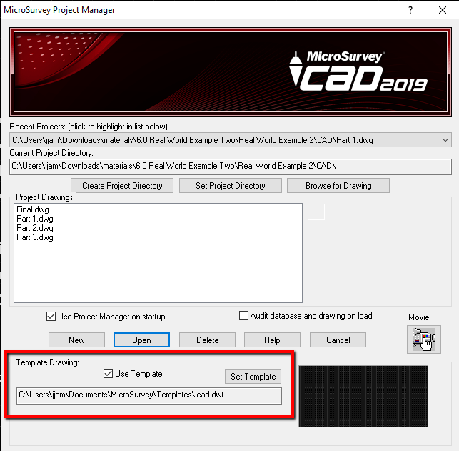
Next, open a new drawing using Project Manager. Ensure that the program is set to use the correct template using the section of the dialog shown below:
Set a Drawing Scale Factor in the General Configuration Options Screen
Set your Global linetype scale (LTSCALE) to match the Drawing Scale factor
Now draw some dashed lines and do some test prints at the correct scale (the one specified in Drawing Scale Factor).
Modify the Linetype scale setting (CELTSCALE) in Settings | Drawing Settings | Entity Creation until you have lines that look just the way you like them.
**NOTE: Changes to Linetype Scale may not be visible until you type regen in the command line. For big changes you sometimes need to zoom in tight before running a regen. If in doubt, closing and reopening the drawing will update the linetype appearance.
Save any changes you make by overwriting your template.
3. Creating New drawings.
From here on, the procedure for opening new drawings is as follows:
- Create the drawing using the template
- Choose your Drawing Scale factor
- Type LTSCALE and set it to match the Drawing Scale factor
- Continue your work
4. LTSCALE and CELTSCALE discussed:
LTSCALE: Use LTSCALE to change the scale factor of ALL linetypes for all geometry in the drawing. If you only plot from Model Space you can use it for your plot scale as well. If you use Layout Space to print you can leave this value to 1.
CELTSCALE: Use CELTSCALE (Current Entity Line Type Scale) is relative to LTSCALE. When you set the CELTSCALE to a value (example 0.5) the next line that is drawn will have a scale factor which is half the scale of the lines drawn previously. This feature is useful for changing the linetype scale as your draw them.
5. LTSCALE as applied in Layout Space
A powerful CAD feature for creating drawings is layout space. This allows you to create viewports and assign a scale to them to match the drawing scale factor. Use the command SCALE_VPORTS for a convenient way to inquire and assign a viewport scale factor. The appearance of special linetypes when you create a viewport in layout space can be handled two ways:
PSLTSCALE OFF: The appearance of special linetypes WILL be affected by the viewport scale. For example, if you have a line with dashes that are 1 unit long in model space, the same dashes will have differing length if you print the drawing with two viewports that have differing scales.
PSLTSCALE ON: The appearance of special linetypes will be corrected so that the appearance is consistent in viewports with differing scales. For example, if you have a line with dashes that are 1 unit long in model space, the same dashes will have the same length if you print the drawing with two viewports that have differing scales.
6. Setting LTSCALE of entities drawn in layout space outside of the viewport:
There are times when you need to use non-continuous linetypes in layout space outside of a viewport, but have the LTSCALE match that of the lines displayed in the viewport. Creating a legend is an example of this requirement. You can accomplish this by drawing the entities and then modifying their properties so that LTSCALE is set as follows:
Imperial Drawings (Printing with inch dimension paper):
CELTSCALE/LTSCALE. (ie: LTSCALE of a dashed line in an imperial 1:100 drawing would be .5/100 = .005)
Metric Drawings (Printing with mm dimension paper):
CELTSCALE/LTSCALE * 1000. (ie: LTSCALE of a dashed line in an imperial 1:2500 drawing would be .01/2500 * 1000 = .004)
James Johnston
Comments