While this command still exists in the current version of MicroSurvey CAD and inCAD, we suggest you use the tools found in the Active Coordinate Editor. The Active Coordinate editor does everyting the Graphic Coordinate Editor does plus much more.
One of the more powerful tools, and yet not used by many of our clients, is the Graphical Editor. This tool allows you to select points in many different methods, and then process the group of points to enact many different changes to the points.
The command can be started by selecting the GraphicEdit button on the Options Bar at the top of the drawing, or by going to the MicroSurvey Pulldown Menu - down to Coordinate Point Utilities - and selecting the Graphic Coordinate Editor option.
The first thing you will be asked for when starting the command from either location, is a Name for the group of points. We are temporarily grouping the points you will select, so that we can process them all at the same time. The name you give here is only a temporary name and does not have to be anything elaborate. Simply naming it as Group1 is sufficient.

After assigning a name (no spaces permitted in the name), press the enter button to proceed.
You will now be presented with the following dialog box. This dialog box now allows you to select points that you need to edit. You may select the points in many different ways, depending upon which method is the easiest for your data.

Lets say that you need to edit some points that are all on the same layer, or maybe points that all have the same description or fall within a specified elevation range. Well all of these options are available to you in this dialog box. You can even mix and mingle the different options to make a more complex selection. You may pick any of the methods, one at a time, but using them in the correct order may make a very difficult set of points, easy to select for editing.
If you need all the points on layer GROUND, as well as all the points between 100 and 200, But you do not want any points with the description of BAR. This would be very difficult to go through and pick manually but with this Graphic Editor routine, it is easy.
Following this example - we would pick theLAYER BY (SINGLE OR MULTIPLE)button to start with.

A list of all layers would appear and we would highlight the layer(s) we require. In this example I am picking on the GROUND layer. After selecting the correct layer, pick the OK button once. This forces the routine to very quickly go out and pick the points. When finished selecting all the layers, you pick the DONE button to return to the previous menu. (NOTE: if the layer you select has no points on it, you will be taken all the way back to the first step of naming the group)
Now that we have all the points on the layer GROUND selected, we need to add the points numbered between 100 and 200. To do this we pick the button markedPOINTNUMBERRANGE. The following simple box appears on screen. It is simply asking you if you wish to remove the point numbers from the current group or if you are adding to the group. We are adding to the group so we do not need to do anything other than pick the OK button.

After picking the OK button - the following prompt appears in the Command area;
Enter Range like: Point#..Point# :
This is where you type in the point range desired - in our case it is 100 to 200. We type this in like this: 100..200 (yes the 2 dots between the numbers is important).
After pressing Enter, the prompt will reappear - simply enter another range if you have another range of points to select, or press enter to end this selection method. We will press enter as we only have one range of points in our example.
You will return once again to the previous dialog box. (it should be familiar to you by now)
The last step in fine tuning our selection set of points is to remove any points with the description of BAR. Manually this could be a nightmare. For us, we will use the button labelled,DESCRIPTIONS (WITH WILDCARDS eg.HP*)This brings up the following dialog box.

You type in the description desired, in our case it was BAR. If you wanted any point with a description starting with BAR but with more information attached to it, such as BAR123 or BAR(SSIB), etc, then you could do as I have shown above, and add the * character to encompass all descriptions where the first 3 characters are BAR and it does not matter if anything follows BAR.
The other very important item on this dialog box for this example, is the little box I checked on asking us to Remove group points with this description. With this turned on, any points with the description shown will be removed from our selection set. If we do not turn this option on then the points would all be added to our selection set. Big difference in the end so be careful.
After picking the OK button you will once again be returned to the previous dialog box.
Now, we have taken our time and carefully selected our points that we needed to edit. These points have all been placed into a temporary group and are ready to be edited.
Pick the button markedPROCESS GROUPto go to the editing options. We can do a lot of different edit to these points. The list is quite comprehensive.
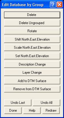
Now that you have your group of points comprised of points from Layer Ground, numbered between 100 and 200 but no points with BAR as a description, what has to be done to correct the points in the way you desire?
Let us assume the following; All the points must be moved to the layer DESIGN, they all need to be scaled by a factor of 0.9967 in the Northing and Easting only, and they need a new description of OG assigned to them.
Fist button to pick would be theLAYER CHANGEbutton. This brings up the following box.

Simply type in the layer name desired, in this example, DESIGN. If the layer does not exist then it will be created for you. You can also control what information actually moves to the layer entered. You pick what you require, in my example I am moving everything to the new layer to make it easy to spot later. Pick OK and the points are instantly moved to the Design layer. You will then return to the previous dialog box.
You can now do the Scale command by picking theSCALE NORTH, EAST, ELEVATIONbutton. This button brings up the following box.

Very simply, you enter in the desired scale factor in the desired fields. In this example the factor of 0.9967 is entered in only the Northing and Easting fields. All scaling is performed numerically and not about any particular point in the drawing. Pick OK and the points are relocated accordingly. You are also returned to the previous dialog box once again so you can do the next edit to the points.
Our last edit required for this example is to change the descriptions to OG. To do this pick on the button markedDESCRIPTION CHANGE.

Type in the new description that you require. When you press the OK button, every point in our selection set will have its description changed to OG. You will then be returned once again to the previous dialog box.
You have now successfully selected points in 3 different ways to obtain just the points that needed editing, and have now edited those points in 3 different ways to bring them to the correct location, on the correct layer and with the correct description. To do this manually would have been much more difficult and taken many times longer to perform.
Now that we are finished editing the points, we have to pick the button label DONE to exit out of the editing options. This returns us to the dialog box where we selected our points.
If you had more editing to do with other points, you could type in a new group name where permitted and then start the next editing session. In our example, we have completed the editing and wish to exit the command. In the bottom right corner of the dialog box you will see a little box markedUNGROUP ON EXIT. Be sure to have this checked on. Then pick theEXITbutton to exit the command.
By checking theUNGROUP ON EXIToption, we force the following dialog box to appear.

We will answer YES to this. If you answer NO then the points will remain grouped together and anything you do to one point will be done to all the grouped points. This can be very powerful but it can also be very confusing and dangerous for the person just learning this tool. Feel free to experiment once you understand the process better.
I hope this gives you a better feeling of how to use the Graphic Editor, and some of the hidden power and flexibility it has built into it. I did not explain all of the options but you will see the way they work is similar to what we have already explored.
NOTE: The new Active Drawing Technology window for coordinates has all of these same options built into it.
Happy Point Editing!
Created on: October 6, 1998
Jason Poitras
Comments