The whole topic of parts can be very complicated to some. In this note I hope to unlock some of the mysteries and make them easier for you to use.
A Part is a group of drawing entities that are classed as a single drawing entity and treated as one. Some examples may include; North Point, Title Block, Posts and Bars, Key Map, Notes, Company Logo, and many other symbols.
To start with, I need to explain that there are basically two different types of blocks.
- Internal- An internal part can only be found inside of the current drawing. It is normally generated so you do not have to redraw the same symbol over again. The internal part can be inserted many times in this drawing but can not be used in any other drawing unless it is converted to an external part, or unless this drawing is used as a template for another job.
- External- Any drawing on the hard drive can be considered an external part. An external part can be inserted into any drawing at any time. You can create an internal part and then save it as an external part (as a separate drawing) or you can create an external part directly from any drawing by selecting what should form the part.
Creating Internal Parts
Let us start by creating an internal part. The first thing you need to do is draw the objects you wish to create the internal part from. Normally you would draw all of your parts at a scale of 1:1 (metric). This way if you insert it into a drawing at a different scale, such as 1:200, then the scale factor is very simple to figure out. In imperial we would draw it at 1"=1' as the base.
As an example, you have a 24"x 36"piece of paper to draw a border on. You have a 1/2"margin on all sides. So you draw a rectangle exactly 23"x 35"in size (this is at a scale of 1"= 1'). Now if you wish to save this border so you can use it in the current job only, then you would use the following command. Under the Part pulldown menu ->Define Part. Here is what you see when you pick this command,
In the bottom left you see a white window with a list of internal parts that already exist in this drawing. If this is a new drawing then this list may be blank. If you pick on one of the names in the list then you can see what this part looks like by looking at the Preview box on the right. This allows you to check the current parts so you don't duplicate one by mistake. In the top left you are asked to fill in the Part Name that you are creating. In this example I am using the name BORDER. That means that when I am done this command, there will be a part called BORDER saved in this drawing which can be inserted only inside this drawing. In the bottom right you can pick from one of three options.
Delete Defining Objects:This will erase the original linework you drew when you drew the part you are defining.
Maintain Objects:The original linework will not be erased when the part has been created. Each line is as it was drawn, separate from each other.
Replace by Instance:The original linework will be erased and a copy of the part will be placed in the drawing in the location where you drew the original part. The part is treated as one object and the original individual lines are now gone.
In most cases you drew the part as a temporary object and you don't need it left as you drew it. You will insert the part where you wish later. So the first option is most common and is how my example will be treated.
Once you type in the part name, pick the OK button to continue.
Next you will be asked a few questions to completely define the part. The Insertion Point is the reference location for placement. In this example of a border I would prefer to insert it based upon one of the four corners of the part. To do this I picked or typed in the INT option which allows me to pick the Intersection of the corner of the border. Once the insertion point has been picked, you will then be asked to pick all of the items that will form the part. Any standard selection method is allowed. Once you have picked all of the objects, press Enter to complete the command.
Insertion base point:INT
of object:
Select objects:
1 selected.
Select objects:
2 selected.
Select objects:
3 selected.
Select objects:ENTER
*** 3 selected. ***
The part has now been saved inside the current drawing - it is now known as an Internal Part. This part can be used as many times as required in this drawing only.
If you already have a part saved by the same name you are trying to use this time, then you will get this warning,

If you answer Yes then the old part will be replaced by the one you are creating. No takes you back to the dialogue and cancel aborts the step.
Creating External Parts
An external part allows us to use it in any number of drawings. To create an external part you can do it one of two ways.
- You can simply draw your part in a new drawing and when you are happy with the final product you can save the drawing. A saved drawing has the extension of FLX. This would assume that there is nothing else in the drawing that would interfere with the part or get inserted with the part, that shouldn't be there. The downside is that you have to either think about and create the part before starting your job or you would have to erase everything that did not pertain to the part - another waste of time.
- The best way is to create the external part from your current drawing, allowing you to continue with the job but save features as parts so they can be used in other jobs at other times. To do this go to the Part pulldown menu ->Write Part File. Next you will see,

This is allowing you to choose the location on your computer where you can save the new part as well as allowing you to name it. In my example I am saving it in the Blocks folder and I am calling it BORDER. The FLX extension is automatically added as this will actually be a drawing file when completed. Hit the Save button once you have the name and location set. We also have the advantage of choosing the file type in the few cases when you may wish to create a DXF or DWG file directly. Do this by picking the Save as Type option and choose the format desired (FLX is the default).
If you try to save your part over a file that already exists then you will see the following warning message,

Now you will see the following,

This dialogue box allows you to do one of three things by selecting the buttons on the right.
PART:If you wish to convert an Internal part to an External part. In other words you have decided that the internal part would be handy to use in other drawings and you don't want to recreate it each time. Pick on the part name found in the list on the left - then pick the Part button on the right. You are done. The internal part has now been saved to it's own drawing file (external part).
ALL:If you wish to save all of the parts out to a drawing so they could all be accessed in that drawing. This is a quick way of copying all of the parts out to a single drawing and then be able to use each part individually in that one drawing only.
SELECT:This does not allow you to pick from the list but it does allow you to create an external part by selecting the objects in the current drawing. This is the same as the prompts for the internal part (in blue above), but will save them in the External Part instead.
You have now created an External Part on the hard drive. It is saved as an FLX file (unless you picked DXF or DWG as your file type).
NOTE:If you insert a part called BORDER in your drawing then create an external part called BORDER which contains the original part. When you go to insert the external part later it will give you the following message.
‚ ‚ ‚ ‚ ‚ ‚ ‚ ‚ ‚ ‚ ‚ ‚ "Part BORDER references itself!"
This is because it now has an internal part within an external part, both with the same name. This is not permitted. You will have to edit the External part as a drawing and rename the internal part, or rename the external part (drawing name) to solve this duplication problem.
Inserting a Part
Now that we have looked at the method of creating both Internal and External Parts, we now need to explore the different options available for inserting the Parts into your current drawing.
There are four commands that allow you to insert parts.
Insert Part -This is the most common of the insert commands. When you pick it the following dialog box comes up.
 ‚
‚
It gives you the ability to insert either and External Part or and Internal Part.
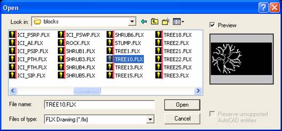
External:
As with any Windows style dialogue box, you need to set the directory or folder to Look In:, then pick from this location to pick the External Part you will insert. You can also change the file type to DXF or DWG and insert that file directly. Once selected, hit Open, and that will return you to the main screen with the name and location of the Part you are inserting.
Internal:
The Internal Part option allows you to choose from any of the Parts already existing in the current drawing. Pick on the part name on the left, a preview will apear on the right to help make the choice easier. Pick on OK when you have picked your Internal Part and that will return you to the main screen with the name of the Part you are inserting.
Once you have chosen the part to insert you then have the option to choose the Insertion Point, Scale Factor and Rotation by typing in the numericvalue in the boxes provided or by picking the Interactive check mark to allow you to pick on screen with the mouse. You can also choose to have the Part Exploded automatically on insertion. Exploding a part means that it is no longer treated as one object and each line that you used to draw it originally, is now available again as separate objects.
Insert Quick -Type the command QINSERT and you will be asked in the command prompt area for the"Part name:". You can either type the name of the Internal Part, or type the full drive/path/file name of the External Part, or you can respond by typing the"?"which brings up the dialogue box shown immediately above under the Internal option. It is meant to be a quick and shortened insert command mainly for internal parts. When using the"?"it is the same as the"Paste Internal Part"command listed below. After picking the part name, via any of the options listed, you will then get the same prompts as shown below in the"Paste Internal Part 1:1"command to allow you to rotate, scale and insert the part.
Paste Internal Part 1:1 -Almost the same as"Insert Quick", this command does not have the command option and goes directly to the same dialogue as shown above. It is for Internal Parts only and always uses the dialogue box. After picking OK you will see on the command prompt the following options;

Pick on Rotation and you will see the prompt;
Insertion point: Rotation
Rotation angle<0>:
Pick on Factor and you get the following options allowing you to determine the size of the Part.

Finally you use the mouse to pick where the part is to be inserted.
Merge External Part 1:1 -This command is actually the same as the"External Part"selection process of the"Insert Part"command above. It is meant as a quick method to insert an External Part so it has bypassed the option of picking an Internal Part. Once you choose the External Part to insert you will then see the same series of Rotation, Scale and Insertion prompts as shown in the"Paste Internal Part"command above.
______________________________________________________________
We have examined how to create both Internal and External Parts as well as the four methods of inserting these parts.
The last section dealing with Parts that we are going to cover is dealing with the Part Library and it's options. First you need to understand what a Part Library is and what it is for. A Part Library deals with External Parts only. The Library will contain many External Parts or FLX drawings in a format that allows you to see the part and some extra textual data to allow easy identification of the part. You can add to a library at any time. You can use the library to quickly group similar symbols and allow you to quickly insert one of the symbols into your drawing.
There are 3 commands that deal with Part Libraries.
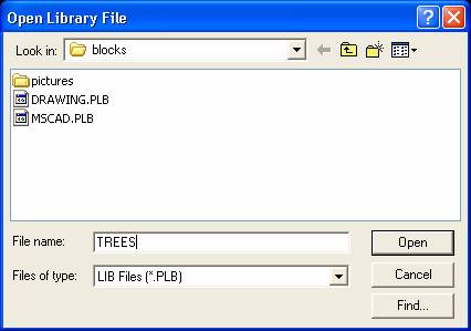
Part Library Setup:This will create a new Library and allow you to add symbols to it. In this example I will create a new library in the following directory C:\MSCAD2002\MSCAD\BLOCK. The Library will be called TREES.PLB and as you may have guessed I am going to add all of the FLX files that are trees, to this library for easy searching. The command brings up the following dialogue box and I have set the directory and file name as mentioned.
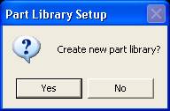
After this I pick the Open button and I will be asked;
 ‚
‚
If the library does not already exist.
Answer Yes and you will see the following dialogue box;
This dialogue helps control what you will see in the Part Library once it is created. They should all be more or less self explanatory. They are all covered in detail in the on-line help file in MSCAD.
Pick on OK and this dialogue appears;
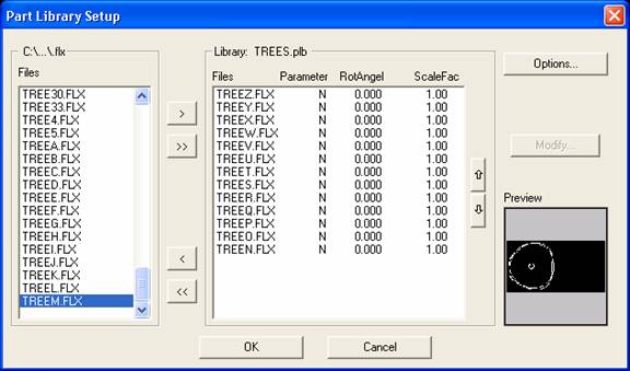
Simply put - the parts in the current directory are all list on the left - you need to pick on each one (Windows selection methods are valid) and then pick the>arrow to add them to the library list. Once all of the desired External Parts (FLX files) have been picked and moved to the right side, pick the OK button to finish this command.
Your Library now exists on the hard drive in the folder you selected at the start of this command.
Set Current Library:This allows you to select which library is current.
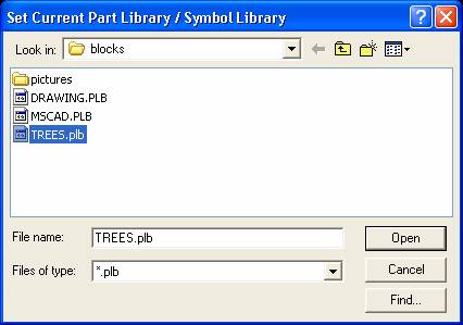
Via the Look In filed you go to the location on the hard drive where the Part Library is located. Then pick on the Library name (TREES.plb in this example) and pick Open. This sets the current library so the next command will work.
Part / Symbol Library:This allows you to insert a symbol from the current library.
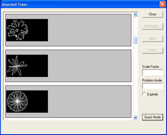
There is a button in the bottom right that allows you to switch over to Quick Mode - if you do then the number of parts displayed changes as shown below,
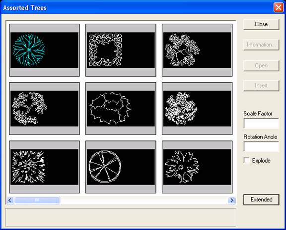
The Extended button returns you to the first screen. Textual information can be added to the External Part entry by picking Information and filling out the form. Close cancels the command. Open allows you to open the FLX into the CAD program for editing (not used in MSCAD). Explode option allows the Part to be exploded into it's original linework automatically upon insertion if on. The scale Factor and Rotation can be changed later and are grayed out for now. The Insert button is the one that allows you to add the chosen part to the current drawing.
At this point you are going to see the exact same prompts as shown above under"Paste Internal Part".
There is another topic dealing with some parts that I am not going to cover here as it is an advanced feature. The topic is Attributes. Attributes are small additions to a part to allow automated insertion of text with prompts to you to control what the text should read each time. Maybe another technical not in the future may cover this topic.
This was a long technical note and it covered a lot of material. I hope it helps explain all the major options dealing with Parts.
Created on: December 7, 1999
Jason Poitras
Comments