While STAR*NET is relatively new to the MicroSurvey product line, our customers have been using the program for decades so a number of tools have been developed over the years that make these two products complement each other. There are a range of importing/exporting options when exchanging data between the programs.
Below a number of options are described which allow for exchange of data between MicroSurvey CAD programs and STAR*NET. These features exist in all MicroSurvey CAD products, including MicroSurvey CAD, MicroSurvey PointCloud, MicroSurvey inCAD and MicroSurvey embeddedCAD.
Exporting Points to a MicroSurvey CAD Program:
STAR*NET can be used to export grid or ground scaled points to a MicroSurvey drawing after they have been adjusted. Descriptions will be included, although some extended point information such as photo notes, voice notes, comments and GIS data will be overwritten in the MicroSurvey database. If points and "smart" lines already exist in the MicroSurvey database they will be updated during the import process and all connectivity will be retained.
Steps in STAR*NET:
When your project is open go to Options | Project | Other Files
Check on "Create Coordinate (PTS) File" and/or "Create Ground Scale Coordinates (GND) File"
For either option, pick on the format pulldown and select "Comma Separated."
Run your adjustment
Steps in MicroSurvey CAD Program:
Open your drawing
Go to MsPoints | Import ASCII Points or Lat/Long File
Select "Coordinates Delimited"
Configure the next dialog as below (Ensure your North, East ordering matches that of the STAR*NET Project)
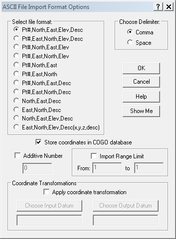
Pick "OK" twice
Navigate to either the PTS (If you need "Grid" system coordinates in your drawing) or GND (if you need "Ground" coordinates in your drawing) file and then pick "Open."
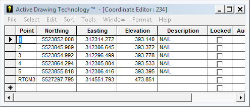
Your drawing and database will now be populated with the new points:
Exporting Points and Graphics to a MicroSurvey CAD Project:
Once an adjustment has been computed in STAR*NET, you can export a dxf file containing all the network lines that were visible in the "Plot" view and open it in any CAD program. Further, you can import the point and line information into the MicroSurvey database and have a "smart" CAD drawing to represent your "smart" STAR*NET network. Some companies have decades worth of fieldwork saved in STAR*NET networks and augment them regularily whenever control points are observed. They are finding that they can add this information to a master MicroSurvey CAD drawing and use "Transfer Points Between MicroSurvey Projects" under the Mspoints menu to export control into new projects. This project can evolve into a great asset for the company, reducing fieldwork costs and improving the resale value of the company.
Steps in STAR*NET:
Open your project and adjust it once.
Open Tools | DXF Exporter...
Configure the dialog as required. I've used Scale and Marker Size settings for a small scale project in this example. You may wish to experiment with different settings for your project:
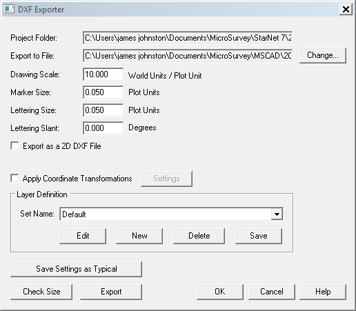
Note that you can customize the layers that will be created during the export by editing the "Layer Definition" file.
Pick "Export" when ready and a dxf file will be created in the location specified in the "Export to File" field.
Steps in MicroSurvey CAD program:
Importing the Point Blocks:
Open MicroSurvey CAD
Open File | MicroSurvey Project Manager
Pick "Browse for Drawing"
Pick on the "Files of Type" pulldown and change it to dxf (Important or you won't see your file)
Navigate to the location of the DXF file you exported from STAR*NET and double pick on it.
| You must zoom to extents before you will see the contents. You will see your network: |
 |
Now you can import the pointblocks into the MicroSurvey database:
Open MsPoints | Other Program Ties | Import Point Blocks
Configure the dialog as below:
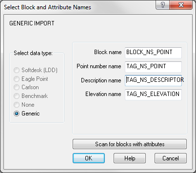
NOTE: The Description Name entry is "TAG_NS_DESCRIPTOR"
Pick "OK"
The next prompt: "Do you want to select Point Blocks to Import" can be answered two ways:
If you select "No" the routine will import all station points into the database
| If you select "Yes" the routine will allow you to select the points to be inserted. Be sure to select the text label for the points, NOT the block that represents the point: | 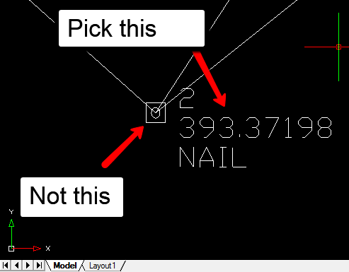 |
The next prompt: "Delete all the Point Blocks after importing into MicroSurvey?" can be answered "Yes" as this will clean up text labels that are now no longer needed.
| Now you can take a look at the result. In your drawing you can see labels have been added: Note: The labels that are drawn for each imported point are sized according to the drawing scale factor that is displayed when you open the project in MicroSurvey CAD. If you wish to quickly re-size these labels open Mspoints | Rescale Complete Drawing and enter a different scale factor. |
 |
| And your Active Coordinate Editor has been populated: | |
Importing the Linework:
For a final step, you will want your network linework to be "smart" linework in the CAD drawing so that linework will update if you import another pts or grd file with updated control points in the future.
Isolate all layers except "ELLIPSES_REL_LINES"
Zoom to extents
Open Mspoints | Auto Add points to Objects
Select all lines
Enter
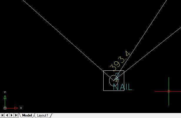
| Now when you pick on any line you will see it is associated with the control point (or in casual terms, it has become a "smart" line.) |  |
Steps to Export Control Points to a New MicroSurvey Project:
Take note of the points that you wish to send to the new project
Open the new project
Take note if there will be any conflicting point numbers in your new project.
Open MsPoints | Transfer points between MicroSurvey Jobs
Navigate to the MSZ file of your "Master" project and pick it.
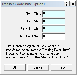
Pick "Open" and you will see the dialog below:
| You can renumber your points if there are conflicting point IDs in the destination project. Or you can retain the existing point IDs by setting the "Starting Point Num:" as zero. You can apply an XYZ shift if you wish, but take care to ensure these points aren't later re-imported into your "Master" STAR*NET project. |
 |
Updating the MicroSurvey Project in the Future:
For future updates to the network just repeat the steps in the "Exporting Points to a MicroSurvey CAD Program" section of this article.
Turn Point Protection on if you want to see an alert when some points shift beyond your project tolerances.
Traverse Data:
Steps in MicroSurvey CAD program:
| Traverses that have been manually entered, created by using the "Existing Point Traverse (new)" routine, read in using theFieldGenius SyncWizard Routine or read in by reading in one of the many supported data collector formats under the MsTraverse Menu can be exported directly to STAR*NET using the STAR*NET Interface. | 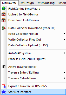 |
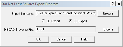
| Export file name: This is where you assign a name and location for the STAR*NET dat file to be created MSCAD Traverse File: This is where you browse inside the MSJ folder of your open project and select the traverse to be exported. |
 |
Steps in STAR*NET:
| This will result in the creation of a STAR*NET format .dat file which can be added to a STAR*NET project. |  |
The first two points in the traverse will be included as C records by default, but you may wish to comment these out and manually enter other points from the project as control.
Point Data:
Steps in MicroSurvey CAD program:
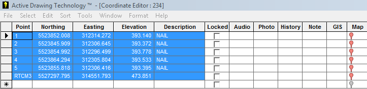
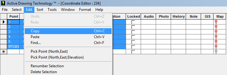
The easiest way to copy individual coordinate values from the MicroSurvey program is to open Active Coordinate Editor and Copy/Paste using Ctrl C/Ctrl V.
Highlight the columns and rows you need to copy:
File | Copy
Steps in STAR*NET
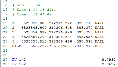
In STAR*NET, open your project, edit the dat file and use ctrl-V to paste the point information:
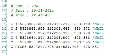
And manually correct the format by adding "C" at the left margin and an apostrophe before the description:
James Johnston
Comments