MicroSurvey offers several different methods of joining points with linework. The points all have descriptions and the descriptions, along with the point number order, help determine what points are joined together.
The different methods are:
Method 1) AutoMAP
Method 2) XYZ Coding
Method 3) SDRMAP Coding
Method 4) AIMS Coding
Lets look at a very simple sample of joining points with straight lines, and compare each method. (There are many codes available for each of the 4 methods, allowing curves, side shots, boxes, circles, etc. This technote only examines the straight line coding option - please refer to the help file for the other coding options available in each method.)
Figure A)

In the above picture, we have 3 points that are collected along a centerline of a road. We have placed the description CL on each point. The road is level and a local elevation of 10 for each point.
Now what do we need to do to get the lines drawn, as shown, using the 4 methods of coding mentioned above?
Method 1) AutoMAP
AutoMAP will join between points that have the same description on them, in an increasing point number order. To do this you must configure the AutoMAP library. The descriptions are entered in the field but the office has to do some configuration to make it work. AutoMAP must start at the lowest point number and proceed through the entire drawing, joining all the points with the same description, in increasing point number order. It can not stop and start individual lines by skipping some points with the same description.
Go under the MicroSurvey pulldown menu -> AutoMAP System -> and pick AutoMAP Library. In this example, we are going to start a new library and enter the CL description and configure it to do the linework. You should see the following dialog on screen:
Figure B)
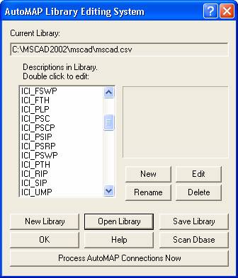
Pick on the New Library button to blank the current list. Then pick on the New button to add the description of CL in the dialog box.
Figure C)

Then pick the OK button to continue.
Next we will see the following dialog. Complete it as shown.
Figure D)
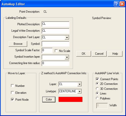
So what does all this do? From the top. Point Description is as was typed in originally. We are telling the program to use the same CL for the plotted description, Legal Writer Description and for the Layer name to place the Description on. We have specified that no symbol is to be placed on this description so we can bypass the rest of the top portion of the dialog. You can decide if you wish to place the Point Number, Elevation or Point Node on the same layer as the Description by picking the appropriate boxes in the lower left of the dialog.
In the lower right we pick on the Connect Points box. We can then choose if they are to be 2D or 3D and Lines or Polylines. This is where we confirm we want linework created for this description. Now that we are creating linework, the last thing to set is in the bottom middle - the Layer to draw the linework on and it's linetype and color setting.
Once you have this all set pick the OK button to continue. This returns you to Figure B) (but the only item in the list will be CL). Now you can save the library so you do not have to do this setup again, by picking on the Save Library Button and following the standard windows prompts.
Now that everything is configured for that description you can now join the linework by picking the Process AutoMAP Connections Now button as seen in Figure B) above. When the dialog shown in Figure E) comes up, pick the Skip XYZ Method button to use only AutoMAP coding.
The next time you use the same description you can load your AutoMAP Library in and simply run the connections.
(Note: we have only shown one description being setup in AutoMAP. Repeating the steps with additional descriptions would allow you to build a larger library. A shortcut in adding description to AutoMAP is the Scan Dbase button - check the help file in MicroSurvey for more info on this.)
Learn more about AutoMap here.
Method 2) XYZ Coding
This method of coding is similar to AutoMAP, in that, a description is placed on each point and we have the option of setting up the dialog in Figure D) so that we can control the layer the linework is drawn on. If we do not setup the AutoMAP layer for the linework then all lines generated will go to the Current Layer in the Drawing.
This routine is different in that we must add a single letter to the front of the description to tell the routine when to start and stop lines. It still joins in increasing point number order BUT we can now skip some points and start a different line if desired.
So the description of CL must have a prefix added to it to control the linework. We have set the letter "Z" to tell it to draw a straight line.
So in Figure A) above, Point number 57 would now require the description ZCL, as would point number 58. Point number 59 is where the line stops so we simply remove the Z, and that point would be simple CL as the description. So the Z tells it to join to the next point number in increasing order with the same base description of CL in this example - then look at the prefix on that description to draw the next segment.
Setting up AutoMAP as described above does add a few nice options. If we setup a single code of CL in AutoMAP. All the points with XYZ codes will automatically use the same layering structure without having to set each code separately for each prefix. The main thing we do not turn on in AutoMAP is the Connect Point box.
If you have set AutoMAP up then this routine will use the settings to control the layering.
If you do not set AutoMAP up at all, you can still join the linework very simply and quickly. All linework will be drawn on the current layer by default.
To run the XYZ Coding (whether or not you have AutoMAP setup), go to the MicroSurvey pulldown menu -> AutoMAP System -> and pick Connect Points by XYZ. As soon as you do you will see the following dialog box:
Figure E)
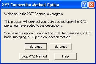
At this point you can decide if you want to draw 3D or 2D linework. (The Skip XYZ Method button can be ignored right now - it also comes up during the AutoMAP method and should be picked only then)
After you decide between 2D and 3D linework, you will then see the following dialog:
Figure F)

If you choose Yes, the ZCL description will have the Z removed and leave you with just CL.
The linework should now be in the drawing either on the current layer (no AutoMAP setup) or on the layers specified in AutoMAP (if you set it up accordingly).
See a movie about XYZ coding here.
Method 3) SDRMAP Coding
This method of coding is similar to AutoMAP, in that, a description is placed on each point and we have the option of setting up the dialog in Figure D) so that we can control the layer the linework is drawn on. If we do not setup the AutoMAP layer for the linework then all lines generated will go to the Current Layer in the Drawing.
This routine is different in that we must add a code to the end of the description to tell the routine when to start drawing lines. It still joins in increasing point number order.
So the description of CL must have a code added to it to control the linework. We add the code ST with a space between the normal description and the code.
So in Figure A) above, Point number 57 would now require the description CL ST, but point number 58 and point number 59 would not require the ST code added. So the ST tells it to start a line and then join all the CL descriptions in the job in increasing point number order. You can not skip any points once you have started the line. The straight lines are all 3D by default.
Setting up AutoMAP as described above does add a few nice options. If we setup a single code of CL in AutoMAP. All the Points with SDRMAP codes added will automatically use the same layering structure without having to set each code separately for each SDRMAP code. The main thing we do not turn on in AutoMAP is the Connect Point box.
If you have set AutoMAP up then this routine will use the settings to control the layering.
If you do not set AutoMAP up at all, you can still join the linework very simply and quickly. All linework will be drawn on the current layer by default.
To run the SDRMAP Coding (whether or not you have AutoMAP setup), go to the MicroSurvey pulldown menu -> AutoMAP System -> and pick Connect Points Using SDRMAP Coding.
The linework should now be in the drawing either on the current layer (no AutoMAP setup) or on the layers specified in AutoMAP (if you set it up accordingly).
Method 4) AIMS Coding
This method of coding is similar to AutoMAP, in that, a description is placed on each point and we have the option of setting up the dialog in Figure D) so that we can control the layer the linework is drawn on. If we do not setup the AutoMAP layer for the linework then all lines generated will go to the Current Layer in the Drawing.
This routine is different in that we must add a code to the end of the description to tell the routine when to start drawing lines. It still joins in increasing point number order.
So the description of CL must have a code added to it to control the linework. We add the code SS with a space between the normal description and the code.
So in Figure A) above, Point number 57 would now require the description CL SS, but point number 58 and point number 59 would not require the SS code added. So the SS tells it to start a line and then join all the CL descriptions in the job in increasing point number order. You can not skip any points once you have started the line. The straight lines are all 3D by default.
Setting up AutoMAP as described above does add a few nice options. If we setup a single code of CL in AutoMAP. All the Points with AIMS codes added will automatically use the same layering structure without having to set each code separately for each AIMS code. The main thing we do not turn on in AutoMAP is the Connect Point box.
If you have set AutoMAP up then this routine will use the settings to control the layering.
If you do not set AutoMAP up at all, you can still join the linework very simply and quickly. All linework will be drawn on the current layer by default.
To run the AIMS Coding (whether or not you have AutoMAP setup), go to the MicroSurvey pulldown menu -> AutoMAP System -> and pick Connect Points Using AIMS Coding.
The linework should now be in the drawing either on the current layer (no AutoMAP setup) or on the layers specified in AutoMAP (if you set it up accordingly).
Remember that we have only examined straight lines for each of the 4 coding methods - there are many other codes available for each method, working in similar fashion to what we have detailed here. More information is also available in the help file for each coding method.
Glen W. Cameron, C.E.T.
Technical Support Manager
Created on: September 27, 2000
Jason Poitras
Comments