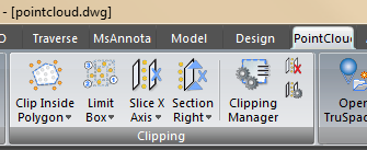
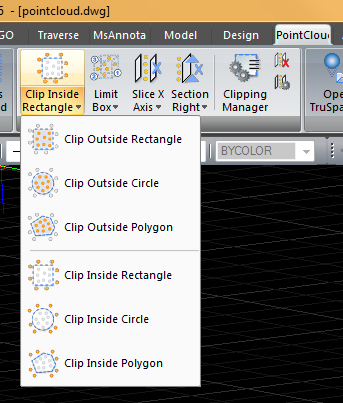
Clip Points Inside
Command: _CWHIDEIN
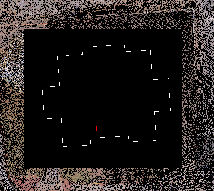
Usage: This command hides all points inside of a user-defined fence. For example, if you wanted to ignore all of the points inside of a building or structure and only display the lanscape surrounding it.
To hide points inside of a fence:
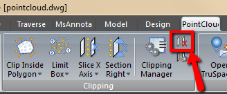
1. Click on the icon or type CWHIDEIN in the command line and press ENTER.
- To change the default type of fence to be drawn, type POLYGON, CIRCLE, or RECTANGLE, and then press ENTER.
2. Draw a fence. If you define a polygon fence, you can end it by clicking near the starting point. The points within the fence are hidden.
- To manage and edit fence clippings, use the Clipping Manager dialog, which is available via the CWCLIPMGR command.
After inside rectable clip"
Clip Points Outside
Command: _CWHIDEOUT
Usage: This command hides all points outside of a user-defined fence. For example, if you were only interested in a certain object, such as one vehicle in a parking lot, you could use this command to hide all of the points surrounding the object or area of interest.
- The procedure for hiding points outside of a fence is identical to the procedure for hiding points inside a fence. See the CWHIDEIN command for details.
Before clipping: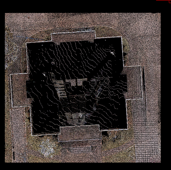 |
After outside circle clip: 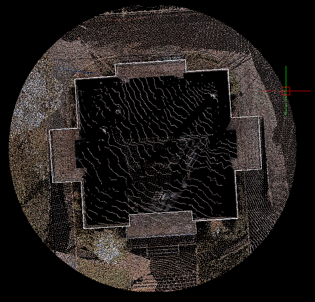 |
Reset Clip
Command: _CWCLIPOFF
Usage: This command erases all the clipping records of the active clipping group, thus restores all the clipped points.
Clipping Manager
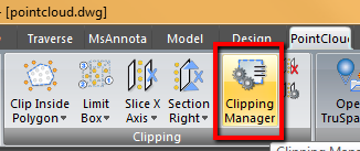
Command: _CWCLIPMGR
Usage: This command opens the Clipping Manager dialog, which is used to create, edit, and delete clipping records.
Clipping Manager Dialog
The dialog has two panes. The left is the list of clipping groups. A clipping group is a list of clipping records that are applied together to the point clouds. You can create, delete or activate a group. At all times there is one group activated. When activated, the clipping records will be displayed in the right pane. In the right pane, you can enable or disable a clipping record. You can invert a section view clipping or a fence clipping too. When you click on the name of a clipping group or clipping record twice, it will allow you to rename it. Note: When cutplanes from Cyclone are imported into MSCAD, only the active cutplane is imported.
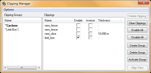
Items in the dialog:
Clipping Groups: List of clipping groups. You can select one and activate it using "Activate Group".
Clippings: List of clipping records of the active clipping group. All the clipping records are applied to the point clouds.
Delete Clipping: Delete the selected clipping record
Clear Clippings: Delete all clipping records of the active clipping group.
Enable All: Enable all clipping records of the active clipping group.
Disable All: Disable all clipping records of the active clipping group.
Create Group: Create a new clipping group. You can click the name twice to rename a group. By creating and activating a new clipping group, the last clipping group is protected. This is because the active clipping group can be easily cleared with a reset clipping command.
Delete Group: Delete selected clipping group. You cannot delete the active one.
Activate Group: Activate the selected clipping group. Clipping records will be updated.
Align View: Align active viewport to face the selected slice (only).
All clipping records are created with following commands:
- Create Limit Box
- Create Section View
- Create Slice
- Create Fence
Limit Box
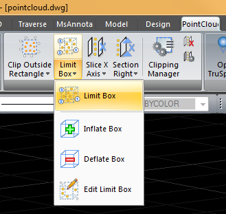
Command: _CWLIMITBOX
Usage: This command is used to define a 3D box beyond which points are not displayed or processed. For example, if you only wish to view the second story of a multi level building you can hide the points below, above and outside of the area of interest.
Note: The limit box does not delete the points. It merely reduces the size and complexity of point clouds for viewing and processing.
To define and place a limit box:
1. Click on the icon or type CWLIMITBOX in the command line and press ENTER. You are then prompted to sequentially enter three data points to define a box.
2. Using the snapping function, select a point representing one corner of the desired 3D limit box (you can also enter coordinates for this corner at the command line and press ENTER).
3. Position the crosshair at the point representing the opposite corner of the desired limit box and click (or enter coordinates for the second corner at the command line and press ENTER). The resulting rectangle is projected onto the work plane.
4. Position the crosshair and select a point to determine the height of the box. If you select the Height keyword, you can also enter the value of the height. Points outside the boundaries of the box are hidden from view.
If all points are hidden after applying the limit box, it is likely that the limit box is defined in an incorrect position. In this case, turn the limit box OFF and try again.
You can use CWCLIPMGR command to turn on or off any clipping records, or use CWCLIPOFF command to turn off all clipping records of the active clipping group.
|
Before Limit Box |
After Limit Box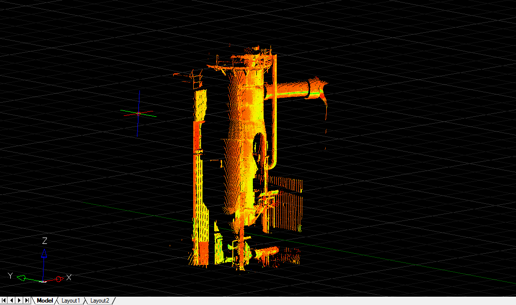 |
Change Limit Box Parameters
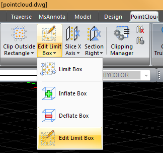
You can also modify the parameters of a limit box, by selecting it in the Clipping Manager, right click and select Modify, which will pop up "Limit Box Parameters" dialog for editing.
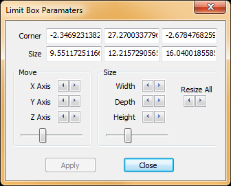
The limit box will be displayed in the view until you close the dialog. You can directly change the values (Corner or Size components) and click another edit box to see the effect. Or, you can use the up/down keys near each edit box. Note that the keys will have different effects. Up/down key for a corner component will move along its axis direction. Up/down key for a size component will enlarge or shrink along each axis in both directions. The "<" and ">" buttons will shrink or enlarge the box in all directions. You can click "Apply" button to apply the change to the points. "Apply" button will be enabled when there is a change. If you "Close" without applying the changes, you will be warned to confirm.
Note, if a change in clipping will expose new area that is previously clipped out, you will be asked to regenerate the point clouds. Such change include clearing one or more clipping, moving slice forward or backward, inverting a clipping or changing a limit box. A message will be displayed with "Don't tell again" option (for the session):
Regenerating point clouds may be required to provide full density in the new area due to clipping change.
Slice
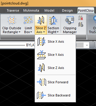
Command: _CWSLICE
Usage: This command is used to define two parallel planes along a specified axis and then hide the points outside the two planes, resulting in a controlled cross-section view of the point cloud. Similar to the limit box, slice allowed the user to isolate an enitre plane. In the example below, all of the points in front of and behind the tower are hidden.
To hide points outside of a slice:
1. Click on the icon or type CWSLICE in the command line and press ENTER.
2. Type X, Y, or Z to select the axis for the slice, and then press ENTER. A temporary line representing the clipping appears and follows the cursor.
3. Click once (or enter coordinates at the command line and press ENTER) to define the first plane. A temporary indicator marks the placement of the first cutting plane, and a temporary line for the second plane follows the cursor.
4. Click again to define the second plane. The points outside the two planes are hidden.
You can use CWCLIPMGR command to turn on or off any clipping records, or use CWCLIPOFF command to turn off all clipping records of the active clipping group.
- See SLICE BACKWARD and SLICE FORWARD commands to move the slice by one step along an axis.
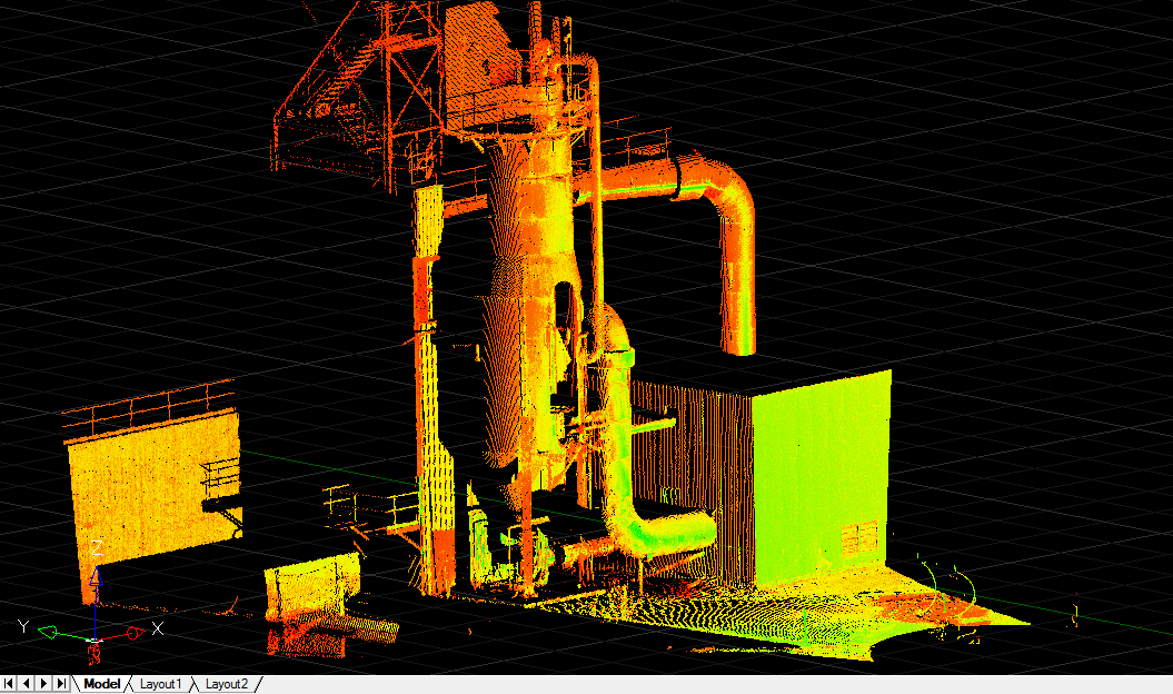 |
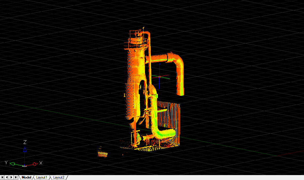 |
See all the Pointcloud training Movies at this page
James Thomas
Comments